GR-ADZUKI GPIO INPUT SAMPLE
入力の使用方法を説明します。
GR-ADZUKIには、2個のボタンが基板上にあります。
プログラムを見ていきます。
まず最初に ボタンの名前とピンの番号を設定します。
ボタンのピン番号は、2、3です。
// set pin numbers:
const int R_button = 2; // the number of the pushbutton pin
const int L_button = 3; // the number of the pushbutton pin
constは、定数を表します。変化する必要がない数値は、定数で定義できます。
intは、整数を意味します。
LEDは、2個使用します。LED1とLED6を使用します。
const int led1 = 6;
const int led6 = 13;
併せて色のピンも定義します。
const int led_R = 22;
const int led_G = 23;
const int led_B = 24;
次にボタンの状態を保存するための変数を定義します。
// variables will change:
int L_buttonState = 0; // variable for reading the pushbutton status
int R_buttonState = 0; // variable for reading the pushbutton status
setup()関数で各ピンの入出力を設定します。
今回、ボタンは、入力なのでINPUTを使用します。ボタンを押したときにGNDにつながる回路になっているのでボタンを押しているとき入力はLOW(0)になります。ボタンを放しているときHIGH(1)にするためにVCCでプルアップします。プルアップする場合は、引数にINPUT_PULLUPを指定します。
loop()関数を見ていきます。
L_buttonState = digitalRead(L_button);
R_buttonState = digitalRead(R_button);
digitalRead()関数は、デジタル入力の状態を取得する関数です。
左ボタン側
// check if the pushbutton is pressed.
// if it is, the buttonState is LOW:
if (L_buttonState == LOW)
{
// turn LED on:
digitalWrite(led1, HIGH);
}
else
{
// turn LED off:
digitalWrite(led1, LOW);
}
ボタンが押されたとき(LOWのとき)、LED1を点灯します。
右ボタン側は、LED6を制御します。
// check if the pushbutton is pressed.
// if it is, the buttonState is LOW:
if (R_buttonState == LOW)
{
// turn LED on:
digitalWrite(led6, HIGH);
}
else
{
// turn LED off:
digitalWrite(led6, LOW);
}
内部プルアップを設定してもボタンの状態が誤動作しました。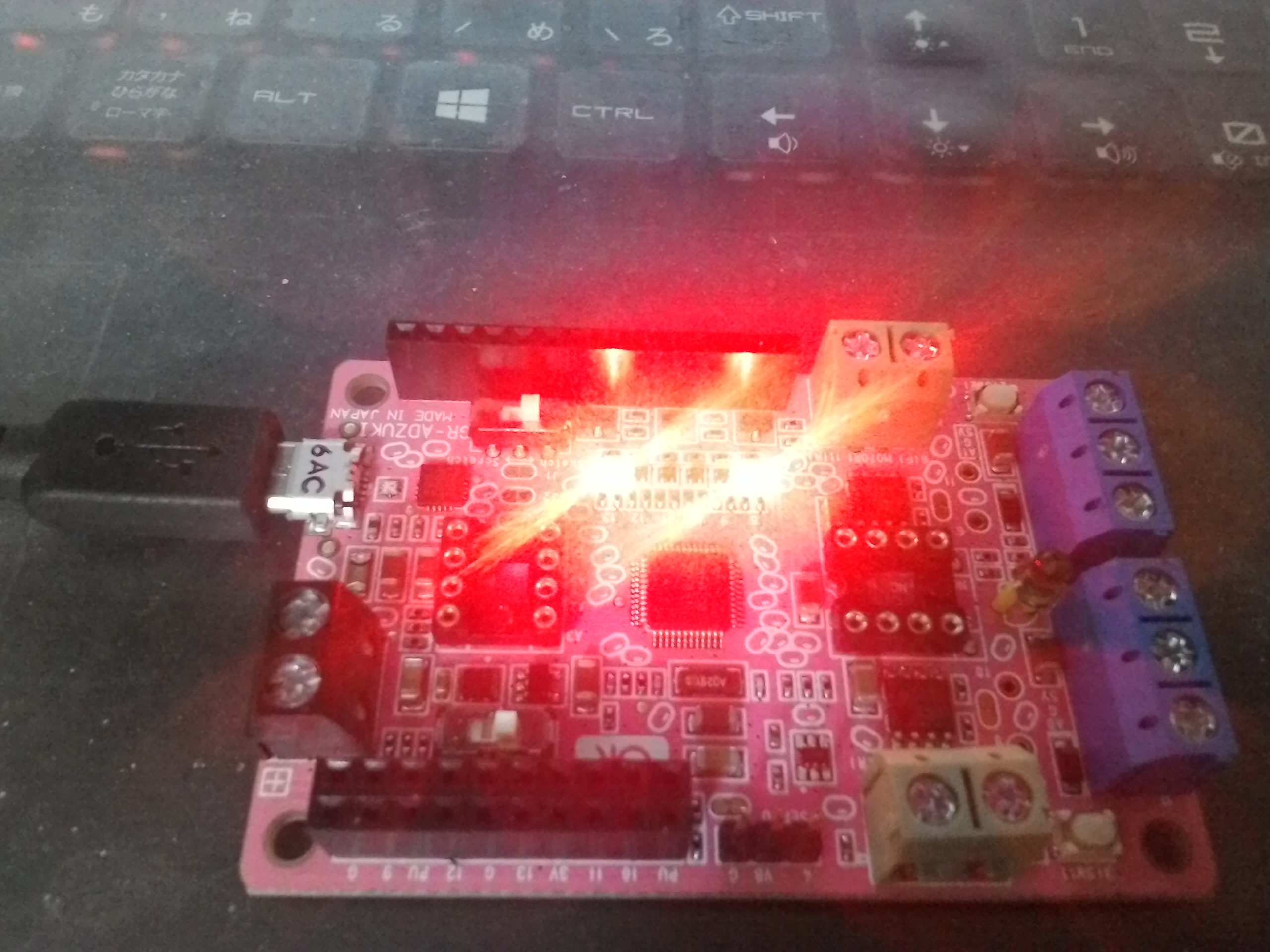
そのため外部抵抗でのプルアップしました。
2ピンと3ピンを1kΩの抵抗で3.3Vのピンを接続しました。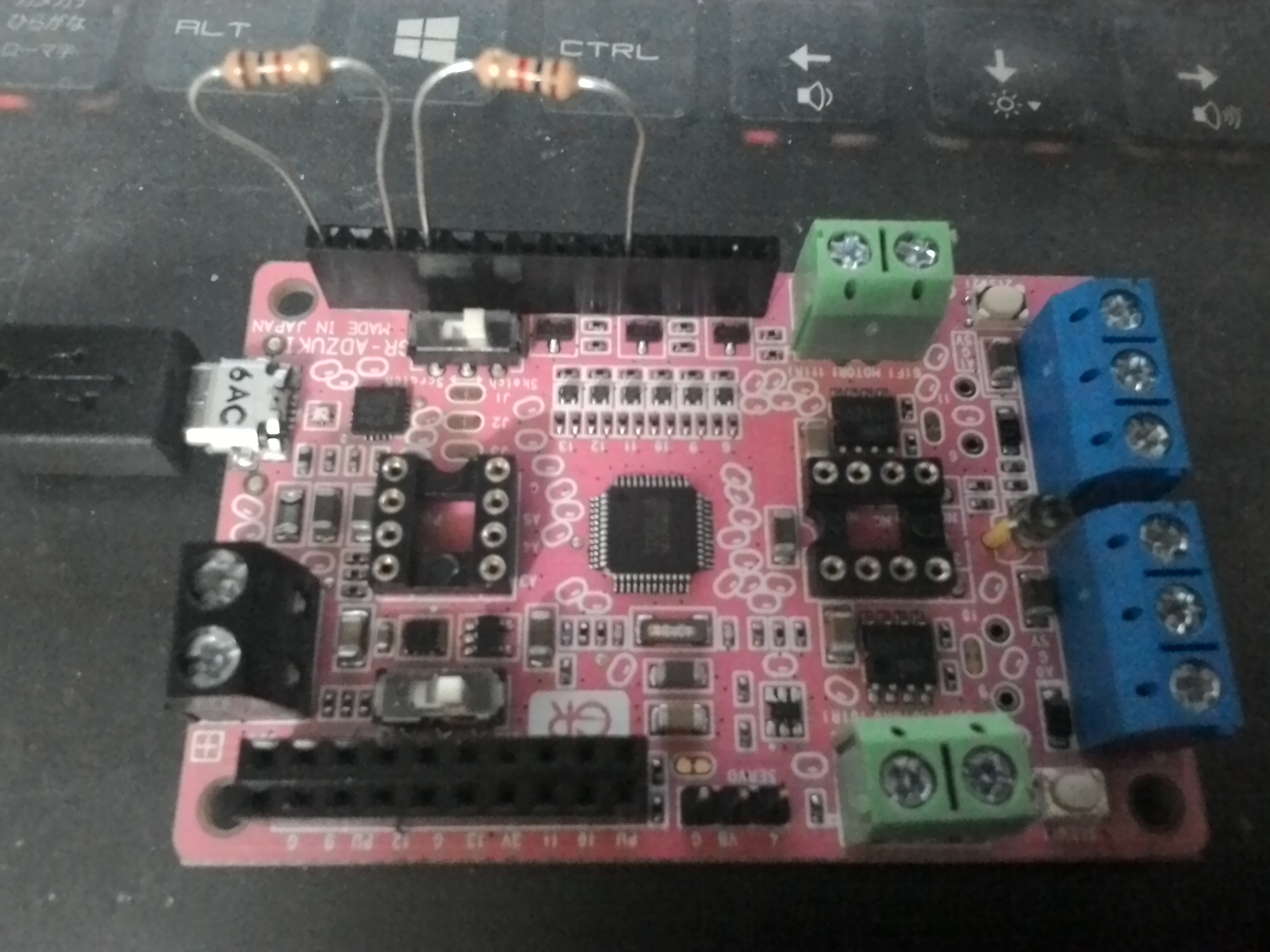
サンプルは以下にあります。
https://github.com/jendo1969/GR-ADZUKI/blob/master/button_LR.ino
I will explain how to use the input.
In GR-ADZUKI, there are two buttons on the board.
I will look at the program.
First set the button name and pin number.
Button pin numbers are 2, 3.
// set pin numbers:
const int R_button = 2; // the number of the pushbutton pin
const int L_button = 3; // the number of the pushbutton pin
const represents a constant. Numbers that do not need to change can be defined by constants.
int means an integer.
Two LEDs are used. I will use LED1 and LED6.
const int led1 = 6;
const int led6 = 13;
The digitalRead() function obtains the state of the digital input.
We also define color pins
const int led_R = 22;
const int led_G = 23;
const int led_B = 24;.
Next we define a variable to save the state of the button.
// variables will change:
int L_buttonState = 0; // variable for reading the pushbutton status
int R_buttonState = 0; // variable for reading the pushbutton statu
Set up the input / output of each pin with setup() function.
Since the button is input, this time INPUT is used. The input becomes LOW (0) when pressing the button because it is a circuit connected to GND when the button is pressed. When releasing the button, pull up with VCC to make it HIGH (1). To pull up, specify INPUT_PULLUP as an argument.
Let’s look at the loop() function.
Left button side
// check if the pushbutton is pressed.
// if it is, the buttonState is LOW:
if (L_buttonState == LOW)
{
// turn LED on:
digitalWrite(led1, HIGH);
}
else
{
// turn LED off:
digitalWrite(led1, LOW);
}
When the button is pushed (when it is LOW), LED1 lights up.
The right button side controls the LED6.
// check if the pushbutton is pressed.
// if it is, the buttonState is LOW:
if (R_buttonState == LOW)
{
// turn LED on:
digitalWrite(led6, HIGH);
}
else
{
// turn LED off:
digitalWrite(led6, LOW);
}
The state of the button malfunctioned even though internal pull-up was set.
Therefore, it pulled up with external resistance.
I connected a pin of 3.3V with a 1kΩ resistor between 2pins and 3pins.
Sample is below.
https://github.com/jendo1969/GR-ADZUKI/blob/master/button_LR.ino
我將解釋如何使用輸入。
在GR-ADZUKI中,板上有兩個按鈕。
我會看看這個節目。
首先設置按鈕名稱和PIN碼。
按鈕針號是2,3。
// set pin numbers:
const int R_button = 2; // the number of the pushbutton pin
const int L_button = 3; // the number of the pushbutton pin
const代表一個常量。 不需要改變的數字可以由常量定義。
int表示一個整數。
使用兩個LED。 我將使用LED1和LED6。
const int led1 = 6;
const int led6 = 13;
digitalRead()函數獲取數字輸入的狀態。
我們也定義顏色引腳。
const int led_R = 22;
const int led_G = 23;
const int led_B = 24;
接下來我們定義一個變量來保存按鈕的狀態。
// variables will change:
int L_buttonState = 0; // variable for reading the pushbutton status
int R_buttonState = 0; // variable for reading the pushbutton status
用setup()函數設置每個引腳的輸入/輸出。
由於該按鈕是輸入,所以這次使用INPUT。 當按下按鈕時,輸入變成LOW(0),因為按下按鈕時,它是連接到GND的電路。 釋放按鈕時,用VCC拉高使其成為高電平(1)。 拉起來,指定INPUT_PULLUP作為參數。
我們來看看loop()函數。
左側按鈕
// check if the pushbutton is pressed.
// if it is, the buttonState is LOW:
if (L_buttonState == LOW)
{
// turn LED on:
digitalWrite(led1, HIGH);
}
else
{
// turn LED off:
digitalWrite(led1, LOW);
}
按下按鈕時(低電平時),LED1亮起。
右側按鈕控制LED6。
// check if the pushbutton is pressed.
// if it is, the buttonState is LOW:
if (R_buttonState == LOW)
{
// turn LED on:
digitalWrite(led6, HIGH);
}
else
{
// turn LED off:
digitalWrite(led6, LOW);
}
即使設置了內部上拉,按鈕的狀態也會發生故障。
因此,外部阻力拉大了。
我在2引腳和3引腳之間連接了一個3.3 V的引腳和1kΩ的電阻。
樣本如下。
https://github.com/jendo1969/GR-ADZUKI/blob/master/button_LR.ino